The peak of an antenna diagram of an antenna may vary from the geometric middle line. This effect is observed particularly in array antennas: even small deviations of the lengths of the supply cables produce phase differences, which impact during the aggregation of the individual radiators and cause a “squinting” the antenna.
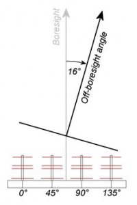
Phased array antennas are antenna arrays in which this effect is specifically exploited. In particular, the phase positions of the individual emitters are controlled in such a way that the resulting antenna diagram deviates from the geometric target direction (“boresight”) by a specific angle, the so-called “off boresight angle” (OBA). Phased array antennas are thus able to pivot their antenna diagram electronically. This has the advantage that the often very large and heavy antenna systems no longer need to be mechanically rotated or pivoted. The electronic pivoting can be performed much faster.
The Phased Array Beam Controller of SkyRadar consists of an array of four individual antennas, each of which is equipped with a phase shifter, controllable through an adjustable control voltage.
ISM (eng .: Industrial, Scientific and Medical band) is the frequency band. The transmitter of this Beam controller operates in the range 2400-2500 MHz. It is the same band in which, for example, wireless network connections (WLAN) work.
Parts
The FMCW Module consists of:
- one (1) Phased Array Beam Controller unit, including
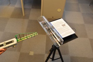 SkyRadar Phased Array Controller and Field Measurement Device
o One (1) graphical user interface to control the beam from a computer (computer not supplied)
o Array of four (4) Yagi-Uda Antennae
o One (1) Phased Array Antenna Controller including four (4) built in phase shifters
o One (1) Tripod
- One (1) field measurement device
- One (1) cable set.
Prerequisites
Extensions
Operations
 Impact of the Phase Shift
The antenna pattern must be measured for physical reasons in the far field. With the above described selected values, the distance of the far field is about 4 m. Thus, the demonstration model is able to operate in a classroom. The field strengths should ideally be measured but from a slightly greater distance than those calculated here 4m: best close to the opposite wall.
The system accommodates four phase shifter modules. These operate in the frequency range 2150-2484 MHz and guarantee a phase shift of more than 180 °. The exact value of the phase shift is adjustable by dc voltage from 0 to 15 volts. Since only a phase shift of more than 135 ° is required, a voltage range up to 12 volts is sufficient.
The respective control voltage is adjusted via a comfortable computer based Graphical User Interface. In the middle position (default 0), all phase shifters are set to zero and all antennas are supplied in phase. The antenna diagram has its peak at the geometric middle line of the antenna.
The maximum output power of the transmitter module is 9 dBm, corresponding to approximately 8 mW.
The power of the transmitter is divided with a power splitter into four equal and in-phase parts. This partial power shares are supplied separately to each of phase shifter module. The total radiated power of the antenna array can be further regulated down by additional attenuators in -3 dB steps
The total radiation of the Phased Array Beam Controller is well below the permitted levels and operating in the lower milli-watt range. It is comparable to the transmission power of such mobile phones that can work in WLAN mode. The impulses of these mobile phones can be tracked by the supplied field strength meter. Once completely outlandish measurement results occur in the classroom, it should be examined whether such mobile phones have distorted the results (or the other way round, try to disturb the results actively through mobile phones).
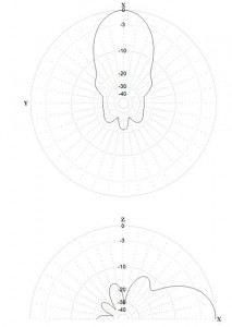 SkyRadar Antenna Diagrams of the antenna array with in-phase power supply;
Technial Data
Voltage Controlled Oscillator
- Frequency Range: 2570 – 3015 MHz
- Power Output: +9 dBm
- Harmonics: -14 dBc
- Pulling (pk-pk) @ 12 dBR: 17 MHz
- Operating Voltage: 10 Vcc
- Operating Current: 35 mA
Phase Shifter
- Frequency range: 2150 -2484 MHz
- Phase Range (Degrees): 180°
- Insertion Loss: 2.0 (Typ.), 5.6 (Max)
- Control Voltage: 0 – 15 V
- Control Bandwidth (DC): 50 kHz
SkyRadar Phased Array Beam Controller
The Phased Array Beam Controller is a radar training module that forms beams through an array of 4 Yagi antennae. The system operates in the milliwatt range and is perfectly save for indoor or outdoor training applications.
Brand: SkyRadar
Manufacturer: SkyRadar
Model: Phased Array Beam Controller
Product ID: SkyRadar Phased Array Beam Controller-Ver.5.0

")